 IK2OFO JN45PB
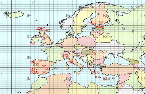
33 SQUARE LAVORATI AL 24/09/2019
SET UP:
IF: ELECRAFT K3
TRV: SPECTRUM COMMUNICATION
TX: 25 W
ANT: 50/70 DUAL BAND ( 6 EL 70 MHz ) G0KSC
G0KSC SC6-4-11D 11el 50Mhz/70Mhz Dual band Yagi Antenna with a 4.9 Metre Length Boom
About this Antenna
This is a dual band Yagi for both 50Mhz and 70Mhz which has a single feed point. This is what is known as an 'interlaced' Yagi as both a 70Mhz beam and a 50Mhz beam (there are no common elements) are interlaced and sitting on the same boom.
The next interesting feature is the fact none of the 70Mhz elements are physically connected to the feed point. The 70Mhz antenna is feed by it's closeness to the 50Mhz elements. i.e. the driven element of the 70Mhz Yagi sitting closely to the 50Mhz driven. It is a little more technical than that but so as the masses can understand how it works. This antenna performs as a 6 element beam on six metres and a 5 element beam on four metres.
You will also note the first director element on 50Mhz is very close to the driven element on the same band. The 70Mhz elements alter the feed impedance of the 50Mhz Yagi and the first director always acts as a tuning device. For this reason, the first director has had to be brought much closer than usual in order for a match to be seen.
The Interlaced OWA design removes these restrictions from the mix. With no losses from matching and just one feed point you have a winning formula!
Design Considerations
Interlaced, single feed point Yagi's are hard to model and there is some interaction between the elements. As a result, I have had to compromise a little more than one normally would have to in order to achieve my performance directives. In this case, I have sacrificed a little Front to Back ratio in an attempt to maintain as flat an SWR curve as possible. There are a couple of reasons for doing this. One, of course is to give as much bandwidth as possible but mainly, as with all antennas on this site, if the SWR curve is wide and low, any small mistakes in sizing and spacing by the builder will not make a tremendous impact on the antennas overall performance.
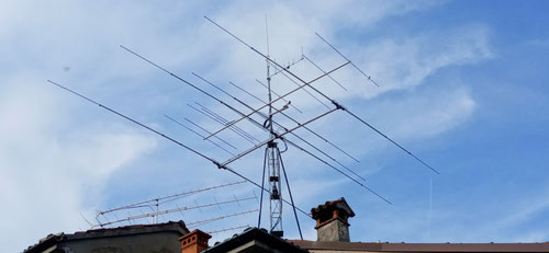
The image below shows how the antenna looks. The 50Mhz and 70Mhz antenna elements are easily seen apart.

Azimuth Plot 70MHz

SWR 70MHz
Sizing and spacing are as follows:
Dimensionsin Metres
Element spacing:
- Ref 6 = 0
- Ref 4 = .255
- Driven 6 = .824
- Driven 4 = .734
- D1-6 = .883
- D1-4 = 1.396
- D2-6 = 1.765
- D2-4 = 2.731
- D3-6 = 3.376
- D3-4 = 4.118
- D4-6 = 4.896
Element sizes per element half:
- Ref 6 = 1.473
- Ref 4 = 1.056
- Driven 6 = 1.456
- Driven 4 = 1.026
- D1-6 = 1.35
- D1-4 = .988
- D2-6 = 1.37
- D2-4 = .947
- D3-6 = 1.339
- D3-4 = .918
- D4-6 = 1.313
Performance figures @ 50.250Mhz:
- Froward Gain: 11.17dBi free space
- Front to Back: 17.18dB
- Radiation angle at 10 Metres above ground: 8 degrees
Performance figures @ 70.250Mhz:
- Froward Gain: 10.55dBi free space
- Front to Back: 14.37dB
- Radiation angle at 10 Metres above ground: 5 degrees
Element diameter:
Each element is made out of single piece 1/2 inch (12.7mm) aluminum tubing Each element half length needs to be doubled in order to gain your total element size. No difference is length needs to be calculated for the 1inch or 1,1/4 inch boom as the elements sit high enough above the boom for the boom to have no influence.